Adding USB to Rudder Pedals
Over a year ago, I bought some second hand rudder pedals for using with flight simulation software. I bought them knowing that they didn't come with the piece of hardware required to connect them to a USB port. They were designed to plug into a flight yoke which would host the smarts to handle the USB chit-chat. My intention was to tear them down and see how they worked to see if I could get simple analogue values out for each of the three axes (two brakes and a rudder), then program a microcontroller to send these values out over USB, acting as some sort of joystick.
This turned out to be simpler than I thought. The pedals came with a DB-9 connector on the end of their cable, and 5 of these connections were used for plain connection to pots already. Ground, positive, and then the three axes' returns. All that I needed to do was remove the complimentary foot cheese and skin flakes that came with the pedals. Nothing a quick dismantle and wash with a cloth didn't get.
For the rest of the electronics, I had an old Teensy 2 lying around. I received it as a gift a number of years ago and I had cut my teeth on it doing "real" microcontroller programming, after having gained my first experience as an early teenager with the PICAXE platform. This poor old thing was starting to get old in the tooth and I thought it was time to put it into something permanent for the rest of its life. Put it out to pasture. Then I can upgrade my junkbox spare to something younger and prettier, and with twice the performance. It turns out that the Teensy folk have been busy, and with Teensyduino, the Arduino IDE had magic menu options to configure the board to act as a mouse/keyboard/joystick. Then, with the addition of some simple lines of code after simply connecting the three pot wiper connections to the first three ADC channels, ground to ground, and positive to 5 VDC:
void loop() {
    Joystick.X(analogRead(1));
    Joystick.Y(analogRead(2));
    Joystick.Z(analogRead(0));

    delay(50);
}
I was ready to go. This is the gist of it, and I am still to do some simple tweaking after I clean the pots in the pedals. Some of the channels aren't maxing out while others are (90% right brake for example). This is likely just dirty pots, but adding small deadzones in the firmware at each end is probably a good idea.
Really, using a Atmega 32u4 for this is in the sledgehammer-walnut zone.
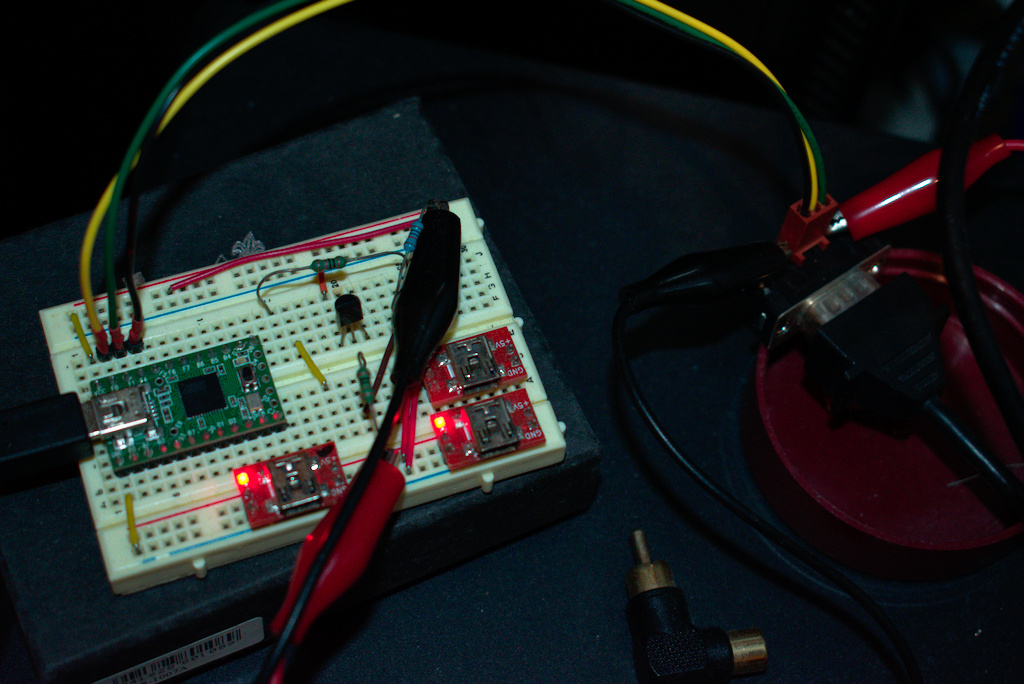
I breadboarded it up and quickly got to flying, feeling relieved at once that I could perform things as routine crosswind landings properly at last. There it sat breadboarded for over a year. Ignore the red boards and unconnected components. Those are unrelated and are just plugged into the board so they don't get lost (I need another tidy-up).
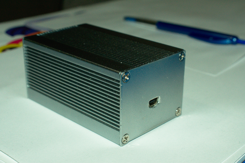
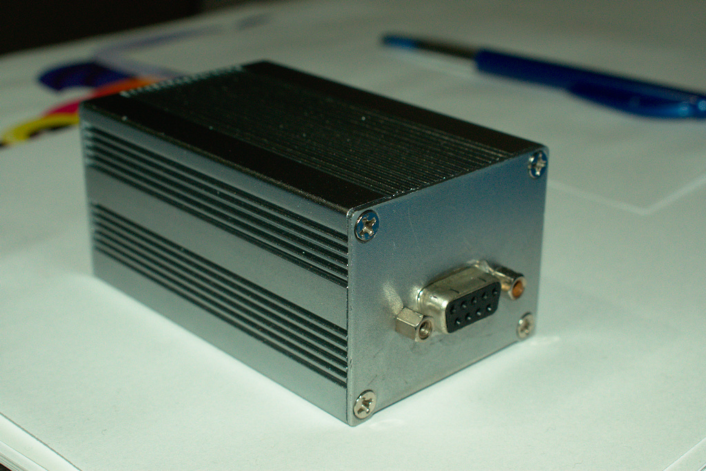
I eventually decided that it was time to solder the thing up and put it in a box, so I did just that. A nice shiny aluminium extrusion with thin end-caps. I know, I made a dog's breakfast out of the holes for the USB and DB-9 connector, but it works and doesn't look that bad.
Bill of materials
The breadboard was replaced with some stripboard for making the connections between the micro and the rudder pedals connector.
- Aluminium extruded box, new: $5
- DB-9 connector, salvaged from equipment, $0. New: peanuts
- Teensy 2, already had. New: box of beer
- 80x46 mm piece of stripboard, already had. New: half a peanut
The total cost starting from nothing is on the order of $20 to $30 depending mostly on the microcontroller platform you chose. There are other systems out there that are used by enthusiasts who make their own 737 cockpits etc, but they were way over the top for what I use (bulkier and have inputs coming out their ears). My solution is cheap, small, and extensible, and I'm quite pleased with it.