16.7 Watt LED Lamps
I'm currently building a couple of high-power LED work lights, using some Cree modules capable of around 2000 lumens of flux. I opted for 5000 K colour temperature because these lamps are for working under, not for mood lighting. I also opted for two parts with identical Vf of 37 V and max VI of 450 mA. Where the parts differ is their CRI ad luminous flux.
I opted for one high CRI (90), which has a reduced flux of 1590 lm, and one lower CRI (70) with an increased flux of 2260 lm The parts also have a sensible efficacy of about 140 lm/W for the low-CRI part and ~100 lm/W for the higher CRI.
Thermal considerations
Heatsinking is a must with LEDs of this power. Some LEDs today will reach as high as 50% efficiency, so when the power of the LED climbs beyond any small amount, some heatsinking is required to move this excess energy away from the device. I am not a proponent of sticking fans on something just because it produces heat energy at all, and I prefer to run heatsinking without fans where it is allowable. They can create undue noise, and can quickly become a maintenance item where dust filtering is not used. Additionally, any moving part can potentially decide to stop moving, so there is the issue of maintenance with respect to bearings or bushings, too.
Knowing this, I investigated repurposing CPU heatsinks for my LED lamps. When coupled with their matching cooling fan, they are often designed to dissipate sometimes up to 80 or 90 W of heat energy for "stock" coolers. Without the fan, some sources on the web recommend a derating their cooling capacity by 90%.
The heat waste that needs sinking from the parts is reasonable. Cree's fine application note on thermal management of their XLAMP parts provides a rough figure of 60% of the input electrical power being wasted as heat, but they recommend a conservative figure of 75%. Much better to slightly over-engineer the thermals than to under-engineer.
The total power of the LEDs is approximately 16.7 W, and using Cree's recommended factor of 0.75 gives a total thermal power of about 12.5 W.
I am unable to run thermal simulations to determine the genuine derating factor when running my chosen heatsinks without fans, nor do I have information on their rated power, since I don't have the equipment they were removed from. It shall have to be determined experimentally. If the chosen heatsinks prove unable to dissipate the required 12.5 W passively, then I am prepared to experiment with running the fans at partial power so that they do not produce perceptible noise.
Electrical considerations
These sorts of LED cobs are popular with other electronics hobbyists, so there is a fair amount of information on the web relating to driving them. Many people buy dirt-cheap 100 W (claimed) modules from eBay sellers, and there have been mixed reviews on them. To drive them, people generally also buy dirt-cheap DC-DC constant current regulators (from eBay again), which are generally based around TI chips like the LM2595 and its cousins. These types of boards are of severely inferior quality and they use fake chips which cannot handle short-circuit conditions, amongst other problems.
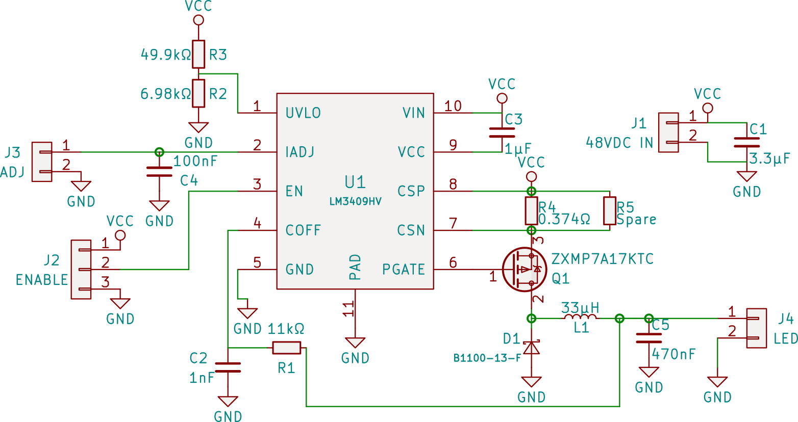
For this reason, I didn't want to touch the boards with a barge pole, and set about making my own driver. For now, I will drop the schematic and a link to the Kicad (eeschema, pcbnew) files. I intend to revisit here once I have built the boards, let some magic smoke out, and revised the design to tell the story from design to high-brightness desk lights.
2019 Update
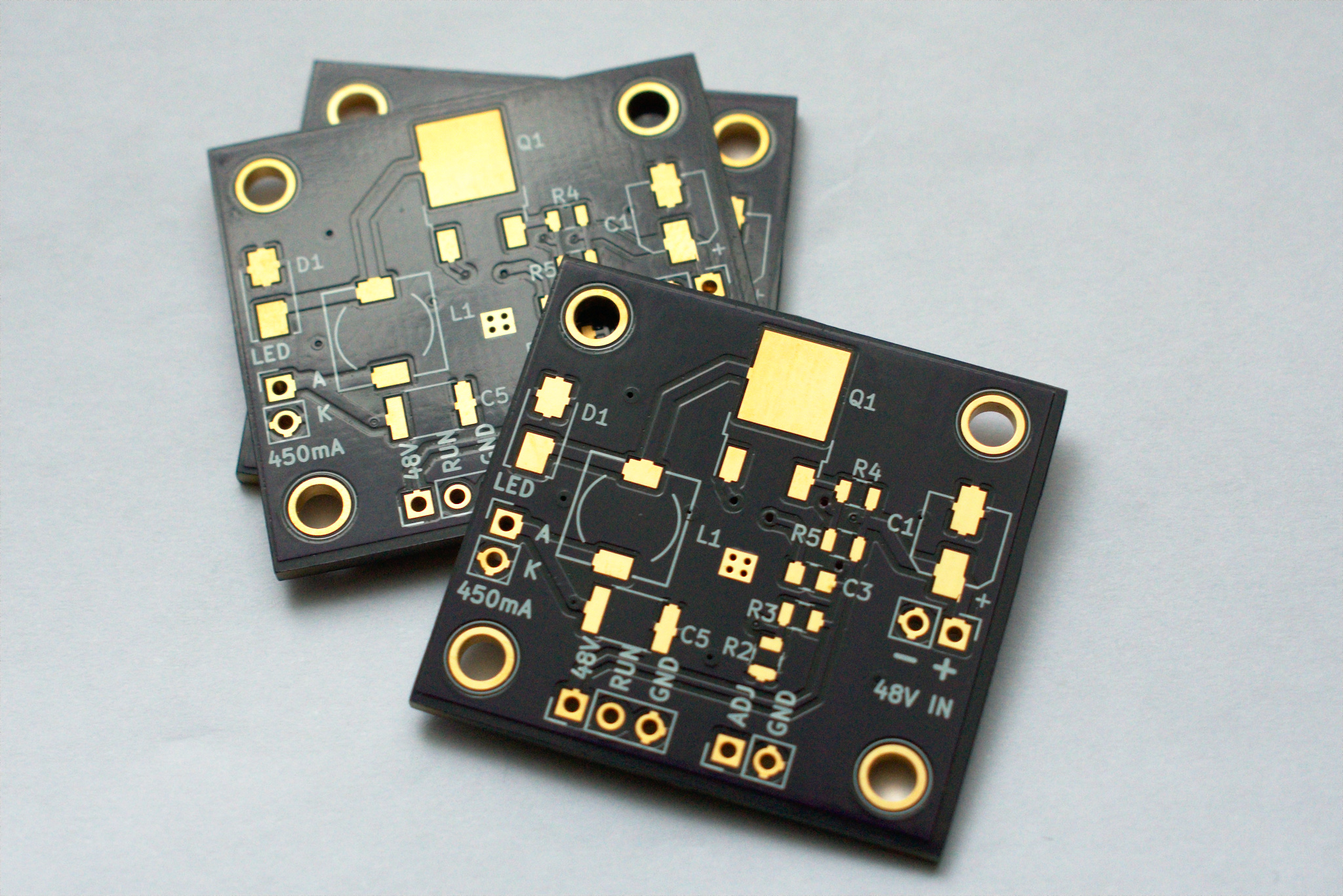
Prototype PCBs
After leaving it far too long, I blew the dust off this project and had the PCBs made by OSH Park in the U.S.A. I only made minor adjustments to the 2017 design on these first revision boards. If memory serves, I moved C5 to the front layer and added thermal relief to pads. This caused problems with the thermal pad of the LM3409 which I could only think of working around for now with polygons or tracks.
The total time from uploading CAD files to the 3 copies of my PCB arriving to me here in New Zealand was 14 days total, or 11 working days. For a volume of only three boards, I think the price of USD$8.50 including delivery is unbeatable.
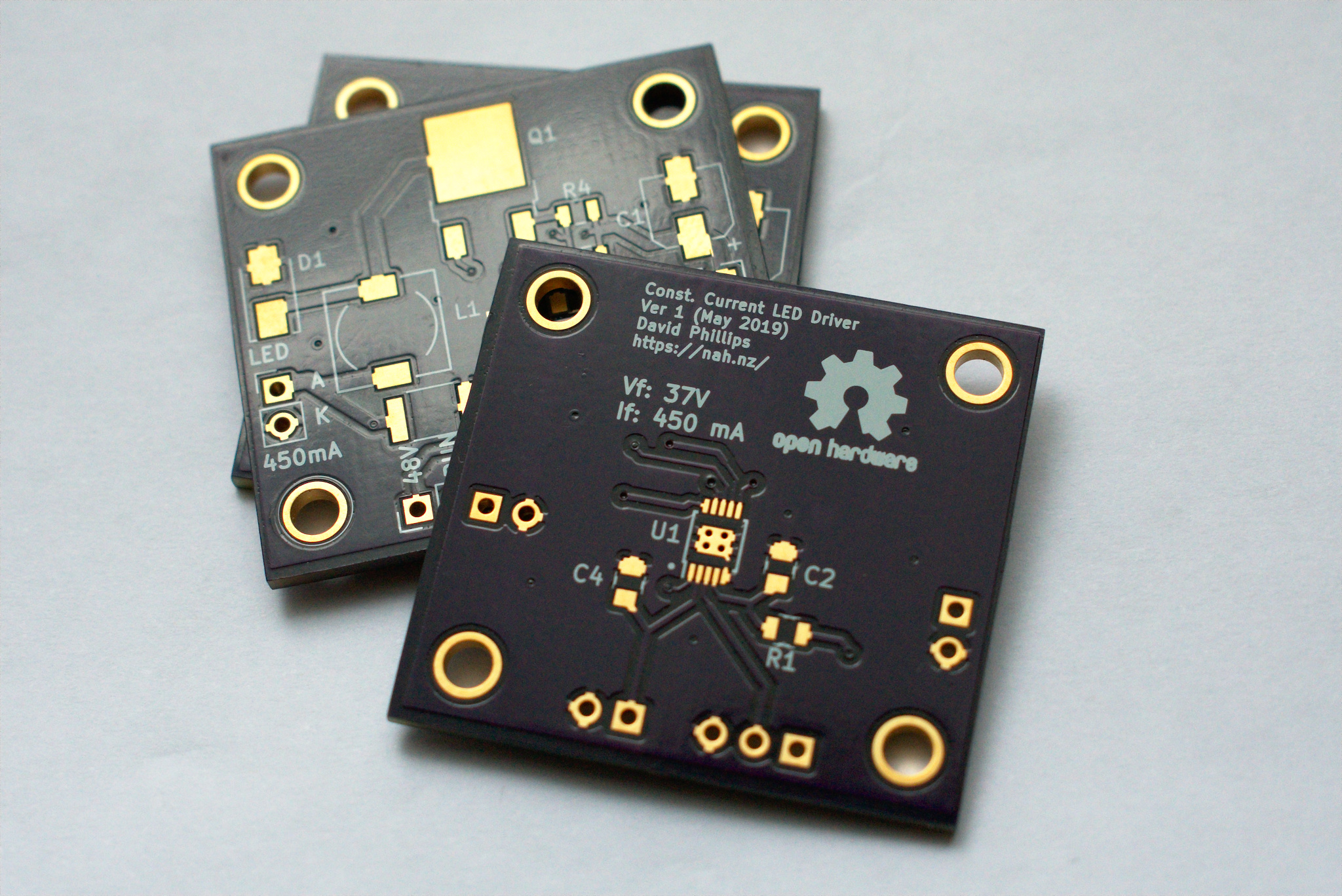
Comparing against some of the boards I've had made at (much lower cost) Asian fabs, the alignment between copper, soldermask, and drill is a lot better (no cross-eyed vias). Additionally, the ENIG finish is a very nice touch, and I'm preferring it to plain old HASL. The silkscreen is beautiful in comparison. The small, bold "open hardware" text came out a little mooshed, but I was going outside the fab's spec when I made it that small. The only other things I noticed was one small mark that looked like an extra drip of soldermask on one of the boards less than 1mm in size, and the alignment between the copper ground plane and the router-cut edges of the board seems slightly uneven between sides.
These are not complaints though. I'm splitting hairs, and the boards cost me only USD$2.80 each, made in the U.S. and delivered to New Zealand. Great quality.
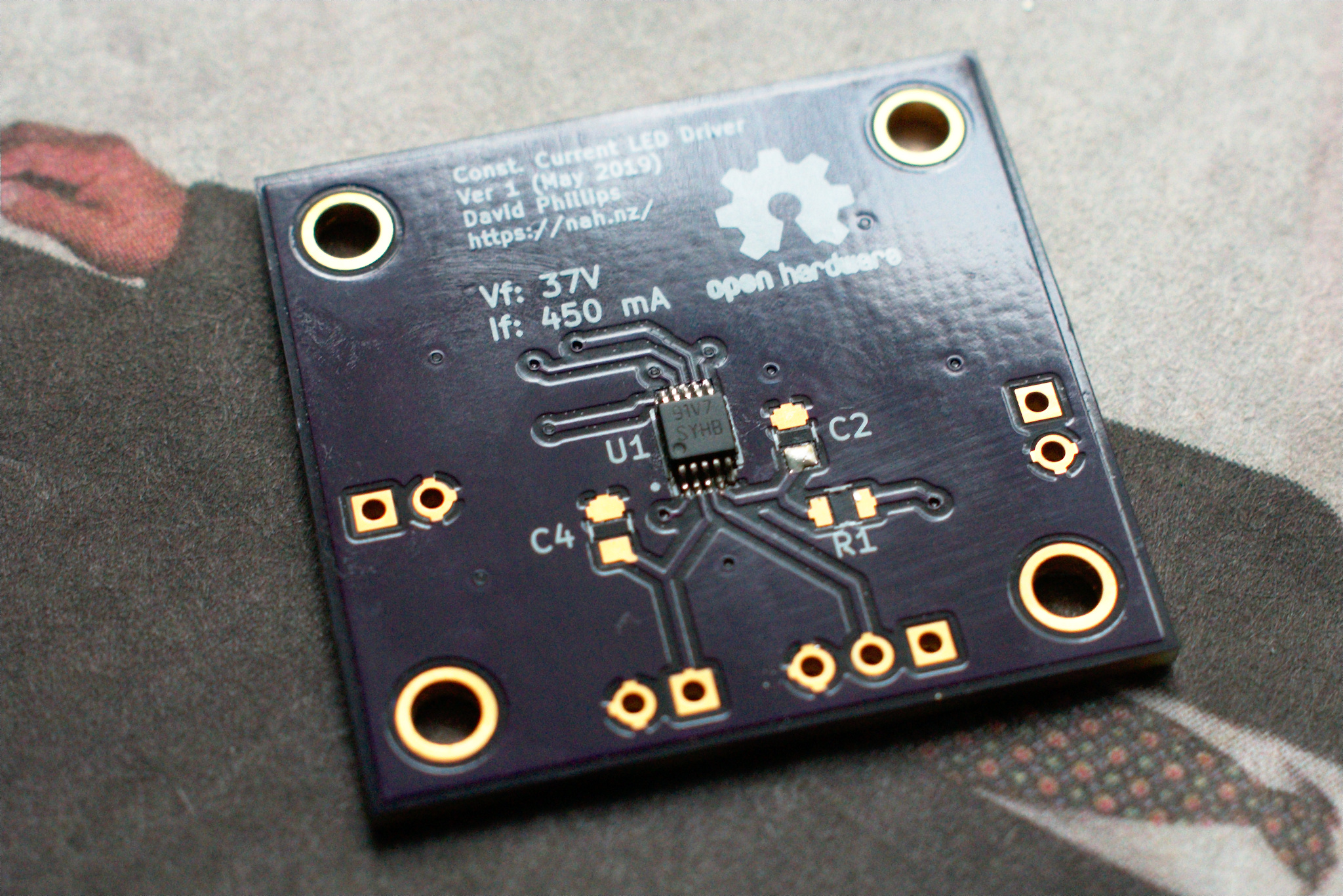
Expecting to find one or two PCB bugs after having sent the CAD files to the fab, I periodically looked at the PCB and was only able to find fault in the lack of soldermask between the MSOP's pin pads. This is more of a nice-to-have, than a must-have and I hadn't researched the fab's capabilities around soldermask this fine, so I didn't sweat.
Soldering the Prototype
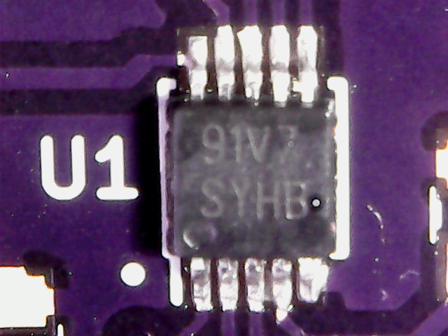
I decided to start with the most difficult and lowest component, the LM3409 itself. I firstly applied solder paste and flux to the thermal pad on the PCB, then placed the chip down onto this and heated this from through the vias on the underside of the PCB. Due to the shape bit I have in my iron, however, I was unable to get the amount of heat I wanted into the joint. I resorted to hot air at 250 °C and had a better time. Only two solder bridges occurred and these were cleared with a good amount of flux and a soldering iron with a fine point. I was satisfied with the end result while looking with no (and weak) magnification, and became horrified with it once under a cheap USB microscope, as is traditional with such low quality sensors.
Excuse the potato quality from the cheap USB microscope:
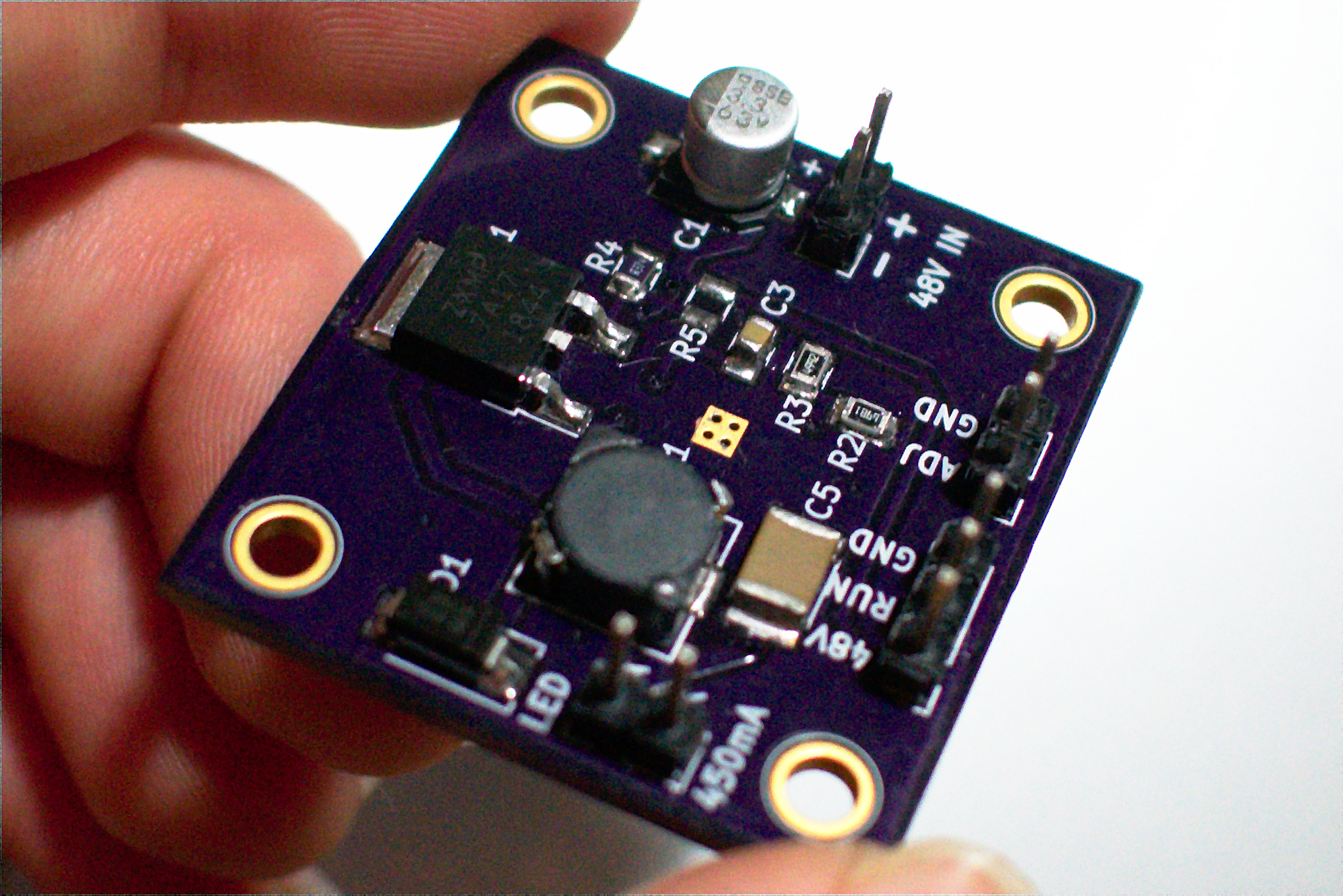
There is nothing worth mentioning for the rest of the board, except that I used a mixture of hot air and hand soldering for it. The end result was a tidy little 34×32mm board with mounting holes and convenient 2.52mm pin headers for connection to various other systems (for analogue or PWM brightness control) as well as to the 48 V power supply and the LED itself.
Current evaluation
On first power-up the board didn't work. I re-read the datasheet for the LM3409 (it's been 2 years after all) and found that I forgot that there is no internal pull-up resistor on the EN (enable) pin. I put a jumper from RUN to 48V and it came to life, sinking 430–440 mA at 40–45 volts into a small dummy load I made out of 50-something 1N4007 diodes stacked in series.
I have been able to make some quick measurements (the dummy load isn't rated for this power continuously, and I haven't mounted the LEDs on heatsinks, so can't use them as loads), and found that for 18.7 W of power pushed into the dummy load, 19.2 W of power will be consumed by the power supply. This puts the efficiency at above 97%. This in itself is impressive, as it is above my design target of 95%. It does warrant more thorough measurement, especially once driving the actual LEDs rather than a rough-and-ready dummy load, but it's amazing to see.
Excuse some of the low quality photos that I took in low-light conditions. I'll re-do them if I can, perhaps once I have one of these LED lights running ☺
Update: More boards built
I had planned on building two copies of my board. However, I had three copies of the PCBs made because that's just what OSH Park does, and I naturally bought at least three copies of each line on the BOM, in case I messed up a board. However, I'm glad to report that two weeks after building the first board, I have built and done preliminary testing of two more boards. I may end up building a third lamp with the spare board, or I may leave it as a hot spare, we'll see. For now I'm more interested in doing some closer performance measurements on the boards to confirm (or not) the 97% efficiency figure.